Reverse Engineering Binary Protocols to Create IPS Signatures
Reverse Engineering Binary Protocols to Create IPS Signatures
The purpose of this article is to demonstrate some tools and techniques used in reverse engineering binary protocols from packet captures, and using the discovered fields and commonalities to create IPS signatures. I decided to write this article as there seemed to be limited information regarding protocol reverse engineering from network traffic and I figured this could be a good resource for people looking to learn more about the process.
Target Selection
Since I didn’t have a specific target in mind when I started this process, I figured it would be helpful to browse through the nmap service probes file to find examples of binary protocols that I could take a look at. https://raw.githubusercontent.com/nmap/nmap/master/nmap-service-probes
The service probes file contains the probe and match statements that nmap uses to fingerprint and identify various services. The nmap documentation outlines how these statements work: https://nmap.org/book/vscan-fileformat.html#:~:text=Nmap%20only%20uses%20probes%20that,describe%20which%20probes%20elicited%20responses
For our purpose, we are just going to search through this document looking for escaped hex sequences “\x” and see which services those are associated with. In this case, I came across the following match statement:
match teamviewer m|^\x17\x24\x0a\x20\x00....\x08\x13\x80\0\0\0\0\0\x01\0\0\0\x11\x80\0\0\0\0\0\0\0\0\0\0\0\0\0\0$| p/TeamViewer/ cpe:/a:teamviewer:teamviewer/
Teamviewer was ultimately a good service to look into as it uses a binary communication protocol for which wireshark does not have a dissector for. Also, some of the protocol and application characteristics provided for some interesting challenges when it came to writing an actual IPS signature, which we discuss later on in this article.
Manual Analysis
The first step of my process involved running the Teamviewer client and collecting some sample packet captures. On startup, teamviewer goes through an initial registration process where it reaches out to a teamviewer master server to register itself and obtain an ID that can be used by another teamviewer client to establish a remote connection. I collected packet captures of multiple iterations of this registration process so that I could compare the traffic and determine if any patterns identified in one capture were specific to that particular connection or if they existed as patterns across multiple connections.
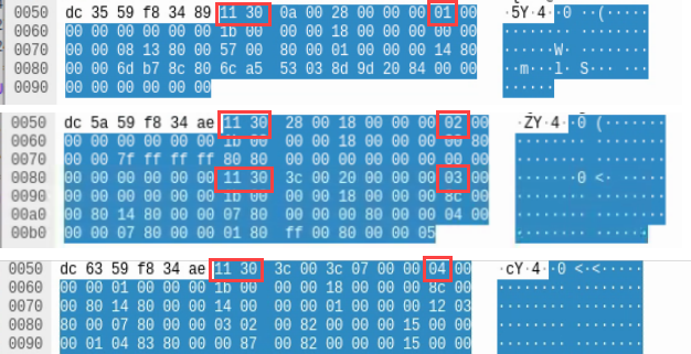
One of the first things that stood out while looking at this traffic, was that the majority of packets’ data started with the same 2 bytes (0x11 0x30). Based on the position of these bytes being the start of the data section and the regularity that they occurred, I determined that this was most likely a magic number. I wasn’t sure at first why this magic number would not be present in each packet, but I was able to make that determination after further investigation. The next pattern that was obvious was the byte following the magic number was more often than not the same value (0x3c). While this this value did reoccur a significant number of times, it had enough variance to indicate that it was definitely not a static value. At this point, I felt I didn’t have enough information about that particular field to label it.
By filtering one of the pcaps to only display client to server traffic and scrolling through the packets, another pattern quickly emerged. For each packet that contained the previously mentioned magic number, the 9th byte would increment by 1, indicating the existence of a counter field. While validating this field, I also noticed that there were occasions when the counter would seemingly skip a number. Looking more closely at each packet, I could see that there were instances where a single packet may contain multiple instances of the magic number and counter field, which accounted for these skipped values. We can see this behavior in the following pcap data.

Summary of Identified Patterns
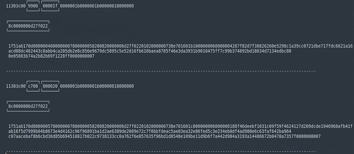
I was able to discover additional patterns in the raw packet data by exporting the data for multiple packets as a hex stream and using a text editor (sublime text in this case) to separate the already discovered patterns/fields and highlight sections of the data that could possibly be additional protocol control fields. Working with the raw data in a text editor made the process of discovering patterns much easier than it had been working directly in wireshark.

Some of the additional control fields that I was able to discover through this process were a message size field, a message start indicator (0x8c 0x00 0x00 0x80), and a message end indicator (0x00 0x80 0x00 0x00 0x07). I also discovered a few additional fields that were clearly a part of the message header, but their function was not obvious based on this limited information I was working with. Finding the message end indicator or trailer was very helpful in determining why certain packets did not start with the magic number identified earlier. Essentially if a message size is too large for a single packet, it could be divided amongst two or more packets and the message trailer is used to indicate the end of that single message.
Validating Findings
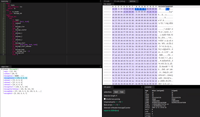
To validate my findings, I first created a kaitai struct that was comprised of all the discovered fields, including the ones with an unknown function.
meta:
	id: teamv
	file-extension: tvs
	endian: le
seq:
	- id: tv_header
	type: message_hdr
types:
	message_hdr:
		seq:
			- id: magic
			contents: [0x11, 0x30]
			- id: command
			size: 2
			- id: message_size
			type: u4
			- id: message_counter
			size: 4
			- id: unknown_1
			size: 4
			- id: unknown_2
			size: 4
			- id: unknown_3
			size: 4
			- id: message_start
			contents: [0x8c,0x00, 0x00, 0x80]
			- id: message_start_unknown
			size: 4
			- id: message_body
			size: message_size - 13
			- id: message_end
			size: 5
I exported various packet data samples from the multiple captures and used the Kaitai Web IDE to validate the struct against them, which helped to quickly confirm that the kaitai struct accurately reflected the protocol structure.

I also wanted to confirm that this structure applied for messages that spanned multiple packets. I created a quick python script to iterate through a pcap and export the message data, when the script encountered messages that spanned multiple packets, it would stitch them together into a single message using the message trailer as an indicator. You can find the script here: https://gist.github.com/scratchadams/e1593c35a7ae754429f77d5afa6ec172
This proved successful, the structure kaitai structure applied for both single packet and multi packet messages.
Creating an IPS Signature
Now that I had an accurate representation of the teamviewer protocol registration process, my next step was to turn that information into a useable IPS rule to block teamviewer from registering with a master server.
Before creating a rule based on the protocol structure, I decided to create a simple suricata rule to block outbound traffic to the default teamviewer port. This was interesting, as blocking the port itself caused teamviewer to adapt and use a combination of HTTP an other port numbers for communication. This was helpful in confirming the effectiveness of the protcol based rule that I ended up creating.
The fields that I focused on to create the suricata rule were the magic number, the message size, the message start indicator, and the message trailer.
drop tcp any any -> any any \
	(msg:"TV Reg Specific"; \
	content:"|11 30 3C|"; \
	byte_math:bytes 4, offset 5, oper -, rvalue 17, result size; \
	content: "|8C 00 00 80|"; content: "|00 80 00 00 07|"; distance: size; sid:1; )
Let’s break this rule down line by line. The first line indicates the action, which is to drop the traffic, as well as the specific protocol to be evaluated, in this case TCP. The first line also has the broad setting of any source IP and port and any destination IP port. The next line is the message displayed in the suricata logs. The third line is a content match on the 2 bytes that make up the magic number and the 1 byte that we will call the ‘command’. Remember this third byte (0x3c) is not a static value, but appeared in the majority of packet samples.
The next line performs an operation on some specific bytes extracted from the packet. This is the message size field being extracted from the packet and the size of the header and trailer being subtracted from that value, the result of this operation is saved to a variable named ‘size’. The final line consists of 2 content matches. The first content match is the message start and the second content match is the message trailer. The distance between these two content matches is also evaluated and must match the ‘size’ variable for the rule to take effect.
Upon testing, this rule proved to be effective in completely stopping teamviewer from being able to register with a master server, rendering the application useless.